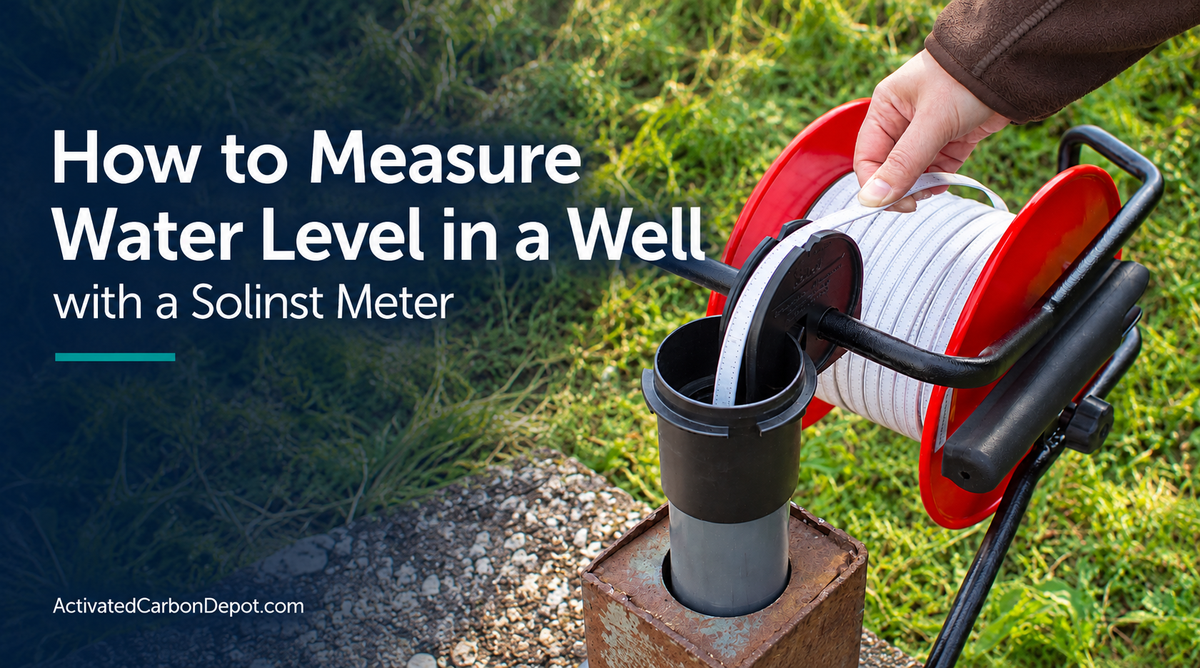
To measure water level in a well with a Solinst meter, lower the probe until the water-contact signal activates, then read the graduated tape or cable at a defined reference point. Confirm the contact position, apply any required tape-guide correction, and record the depth with its units, time, and measurement reference.
The reading is a distance below that reference point. It is not automatically the well’s total depth, the height of the water column, or the water surface elevation. Understanding that distinction makes your measurements easier to compare and interpret.
This guide from Activated Carbon Depot explains a practical workflow for manual readings with the Solinst 101 P7, 101 P2, 102 P10, and the 101D in Water Level mode. Use the operating instructions for your exact meter and your project’s field procedure alongside this guide.
What You Need Before Measuring
- A working water level meter with sufficient tape or cable length
- A clean probe and an appropriate tape or cable guide
- A field sheet or digital record for readings and observations
- The well identification and designated measurement reference point
- Information about installed pumps, tubing, and other access restrictions
Choose equipment for the deepest expected reading, including possible pumping-related decline. A meter that reaches today’s water surface may not reach the lowest level anticipated during your work. Also check probe clearance along the entire access path rather than only at the top opening.
Step 1: Identify the Well and Measurement Purpose
Confirm the well ID before opening your field record. Note whether you are collecting a routine observation, a pre-pumping baseline, a pumping water level, or a recovery reading. These represent different conditions, even when taken from the same well.
If you need a static water level, follow your project’s requirements for pumping status and stabilization. Turning a pump off immediately before measuring does not, by itself, establish that the well has returned to static conditions. Record the operating conditions that affect interpretation.
Step 2: Establish a Consistent Reference Point
Use the designated measuring point, such as a marked location on the casing. Record what that point represents. A depth measured below the casing top should not be labeled as depth below ground unless you have made the appropriate reference correction.
Consistency matters across operators and visits. For example, a later reading taken from the top of a protective cover cannot be compared directly with an earlier reading from the inner casing without accounting for the difference between those reference points.
Keep the reference description with the reading. A number such as “24.6 ft” is much less useful when nobody knows where it was measured from.
Step 3: Check the Meter Before Deployment
For the 101 P7 and 102, Solinst’s equipment checks include testing the battery and main circuitry, followed by a probe-contact check in tap water. The battery test alone does not test the full tape or cable and probe assembly. Follow your model’s instructions and the project’s cleaning procedure when performing the check.
Inspect the measurement markings and equipment condition before collecting data. If the meter does not respond as expected, resolve the problem before relying on its readings. A successful battery check is not a calibration certificate or proof of overall measurement accuracy.
For the 101D, confirm that Water Level mode is selected when taking a depth-to-water reading. Its DrawDown mode uses a different alarm behavior.

Step 4: Position the Reel and Guide
Arrange the equipment so the tape or cable feeds into the well without rubbing a sharp edge. Support the reel according to its size and operating instructions. Do not assume every reel can hang from the casing in the same way.
The guide also establishes a reading position that may differ from your reporting reference. Identify that difference before lowering the probe so you know whether the recorded measurement will need correction.
Step 5: Lower the Probe and Locate Water Contact
Feed the tape or cable gradually and keep control of the reel. Avoid forcing the probe around an obstruction. A stopped probe does not establish that you have reached the water surface or the well bottom.
On standard water level operation, the light and buzzer respond when the probe’s detection point reaches conductive water. Locate the transition carefully instead of taking a reading after lowering the probe well below the surface. Raise and lower it slightly to confirm the contact position, following the instructions for your model.
If the signal is inconsistent, investigate before accepting a reading. Conditions such as moisture at the sensor or water entering above the actual surface can complicate interpretation. Follow the manufacturer’s sensitivity and troubleshooting guidance rather than treating every alarm as a confirmed water level.
Step 6: Read the Tape or Cable and Apply the Guide Correction
Read the graduation at the established measuring position and record the units. Check that the tape is not slack and that your reading corresponds to the confirmed water-contact position.
Solinst’s standard guide instructions describe an offset above the casing reference. When that setup applies, subtract the offset indicated on the guide to report depth below the casing. Use the marking and instructions for your actual guide; do not apply a correction from memory or subtract it twice.
Example: Correcting a Reading Taken at the Guide
| Item | Example Value |
|---|---|
| Reading at guide | 42.37 ft |
| Guide offset above casing | 0.20 ft |
| Corrected depth below casing | 42.17 ft |
This example applies only when the guide’s reading point is 0.20 ft above the casing reference. If your setup differs, use its documented geometry and correction. Keep both the original reading and correction in your field record when required.
Step 7: Record Conditions and Confirm the Result
A useful field record connects the measurement to the conditions under which it was taken. Include:
- Well ID, date, time, and operator
- Meter identification and measurement units
- Reference point and any correction applied
- Original and corrected readings, as applicable
- Pumping, recovery, or other relevant operating conditions
- Unusual observations and any difficulty confirming contact
Repeat the observation as required by your procedure. If readings differ, determine whether the water is moving, the reference changed, or the measurement technique needs adjustment. Do not average unexplained discrepancies and label the result reliable.
Step 8: Retrieve, Clean, and Store the Meter
Rewind carefully and keep the tape or cable organized. Follow the model-specific cleaning instructions and your site’s decontamination procedure, especially when moving equipment between monitoring points. Basic routine cleaning should not be assumed to satisfy every project’s cross-contamination controls.
Keep the reel out of the water. Probe submergence limits and reel protection are separate specifications. Inspect the equipment after retrieval and store it so the probe and measurement markings are protected.
How to Calculate Drawdown from Manual Readings
Drawdown is the increase in depth to water relative to an initial reading, using the same reference point. If the baseline depth is 18.40 ft and the pumping reading is 21.15 ft, drawdown is 2.75 ft.
The Solinst 101D also provides a dedicated mode that signals when falling water exposes a probe positioned at a selected depth. That alarm is a threshold indication; it does not automatically calculate or log drawdown.
Which Solinst Meter Fits Your Measurement?
- 101 P7: laser-marked PVDF flat tape with a pressure-proof P7 probe.
- 101 P2: heat-embossed polyethylene flat tape with a P2 probe.
- 102 P10: narrow coaxial cable and a smaller P10 probe for restricted-access applications.
- 101D: water level measurement plus selectable drawdown threshold detection.
If your procedure also requires temperature and conductivity profiling, consider the Solinst 107 TLC Meter. Its measurement and stabilization procedures differ from a basic water-contact reading.
Frequently Asked Questions
Does a water level meter measure total well depth?
A water-contact reading identifies depth to water. Total well depth requires an appropriate separate measurement procedure and equipment. Do not lower a water level probe to the bottom merely to infer well depth.
Does a deeper reading mean the water level has fallen?
Yes, when both readings use the same reference point: a larger depth-to-water value means the water surface is farther below that point. Confirm consistent units and corrections before comparing readings.
Can I calculate water surface elevation?
If the measurement reference has a known elevation, subtract the corrected depth to water from that reference elevation. Use consistent units and the project’s required vertical datum. Without a known reference elevation, the depth reading alone does not establish water surface elevation.
Does graduation spacing equal measurement accuracy?
No. The distance between markings is separate from the instrument’s accuracy specification. Reading technique, contact confirmation, reference consistency, and equipment condition also affect the measurement.
Do these meters automatically record results?
The models discussed here require operators to record manual water level readings. Choose a suitable datalogger separately if your project needs unattended records over time.
Find a Solinst Meter for Your Fieldwork
Browse the Solinst collection at Activated Carbon Depot or contact our team with your required length, measurement units, access clearance, and measurement task. We can help compare configurations and confirm availability before you order.
Shop Solinst Water Level Meters
Explore the Solinst meters covered in this guide and select the configuration for your fieldwork.